Precision Drivetrain
I designed a precision differential drivetrain platform with stepper motors from scratch. Features Quintic Hermite Spline path generation and pursuit, & control over WiFi.

Introduction
After 3 years of high school robotics, working primarily on differential drives, I was slightly frustrated by the inaccuracies stemming primarily from elementary mechanical tolerances. Considering that I was about to graduate from this level of high school robotics into my undergraduate studies at Berkeley, I decided to undertake this project to formalize all that I learned into a 'from-scratch', 'start-to-finish' differential drive system where I had control over every single step along the design process.
Design Process
My first step was to decide on the motors I wanted to use. I had it narrowed down to two options. Firstly, I could go the brushed motor route (very similar to what I had done previously in FRC), characterize the motors and determine a voltage-velocity equation and solve for the arbitrary constants, then design and tune a velocity PID controller. Although familiar, I really wanted to take my precision and accuracy up a notch, so I decided to go the second route. The second option (that I picked) was to use stepper motors, which are inherently accurate and precise (assuming the load isn't too large), since I would just be able to tell the motors to go to a velocity and assume they reached it semi-instantaneously. An added benefit was not having to worry about encoders.
This design choice came in the form of NEMA-17 motors and DRV-8825 stepper drivers. Electronics-wise, I decided on using an arduino nano for interfacing with the stepper drivers, and a raspberry pi for all the higher-level control and controller interface.
I then designed and 3D-printed the precision platform, seen here:


You can find the source code for base control (for both the arduino & RPi) on my github.
I also created a custom drive controller board that handled the interface between the arduino nano and the DRV stepper drivers:


By this point, I could drive the robot with an xbox controller by using some simple differential drive logic to map the joystick values to velocities for the left & right sides of the drivetrain.
Path Generation & Pursuit
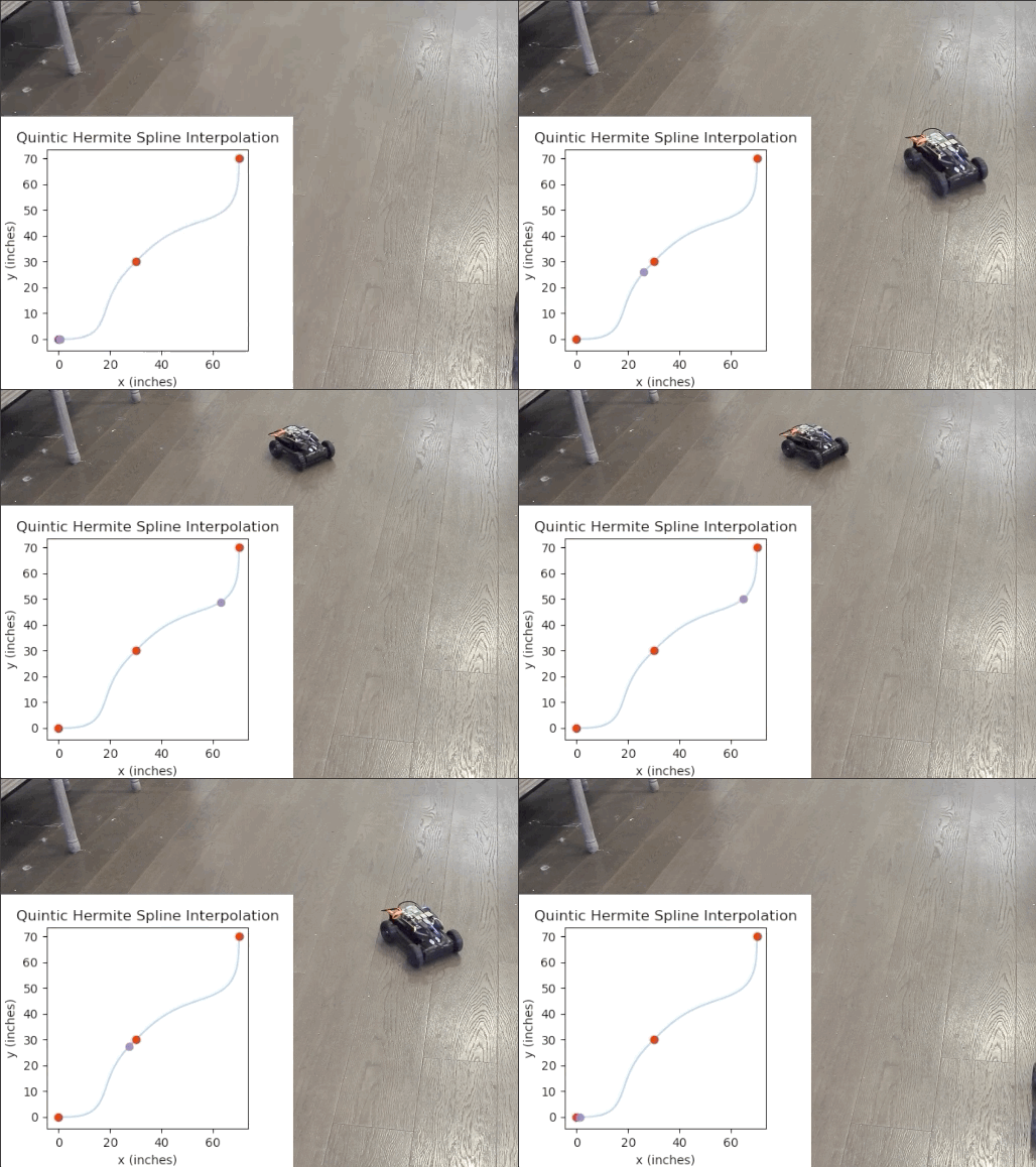
Now that I had a working drivetrain that I could precisely control, I decided to implement a path generation and pursuit suite. The basic premise is as follows: I wanted to be able to select waypoints with a specified heading (global yaw), and the suite should find a continuous path of continuous curvature (since this is a differential drive after all) constrained by the selected waypoints. Then, I wanted the suite to create a time-parametrized trajectory from the aforementioned path using the velocity and acceleration constraints of the platform.
This didn't turn out to be trivial. After doing some research, I decided that I wanted to use Quintic Hermite Spline interpolation to determine the path, since it is the only option that I could find that had C2 continuity (curvature continuity) & properly constrained the output path to the given waypoints and their specified tangents. The more popular options (i.e. Bezier Curves & Cubic Hermite Splines) either only had C1 continuity (which would result in jerky turning) or didn't actually constrain the path to the points, rather merely getting the path somewhat close to the points. The below chart summarizes the clear disadvantage of cubic splines quite well, and this paper outlined the choice for quintic hermite splines clearly.
Note: If there is only one polynomial segment, the spline is often called a Bézier curve. If each segment is described by its ending positions and derivatives, it is said to be in "Hermite" form.

Then, it was just a matter of using a trapezoidal motion profile to find the corresponding velocity and acceleration for evenly spaced points to create a trajectory. But wait! Evenly spaced points? Well, it's quite hard to derive a fully continuous trajectory function, so what I did was determine the acceleration and velocity for a whole bunch of evenly spaced points on the path, then during runtime, I sample this model of the trajectory by passing in the elapsed time since the trajectory started, and I have a sample method that returns the estimated desired velocity by using simple linear interpolation. Since I have an excess of ~1000 control points on average, this is definitely more than accurate enough and it keeps this entire process fast enough to be sampled runtime.
Just because I like matplotlib (who doesn't?), I decided to make a simple visualization tool so that one can preview the path & trajectory before actually deploying to the robot. Note: Keep in mind that the trajectory animation isn't 100% accurate, since matplotlib sometimes takes more time to plot the animation than the desired timestep.
You can find the source code for the visualization tool on my github.
The file to run is test_interface.py
Here's a little demo:
Some fun!
I wanted to make a visualization tool for deriving quintic hermite splines, so while messing around with desmos, I decided to show all the control points, hermite basis functions, xy position/derivative/second derivative functions on the same plot. I found this to be quite aesthetically pleasing.
